Micromouse Maze-Solving Robot
I wrote the C++ firmware for Stony Brook's 2026 micromouse robot, adapting the open-source UKMARS architecture to our Pi Pico robot, and it ran 2nd at NYIT 2026 with a 38 s run. The largest accuracy fix, feeding encoder yaw instead of IMU yaw to the turn controller, cut worst-case spin error from 2.75° to 1.01°.
The problem
A micromouse is a small autonomous robot that explores an unknown maze, then races to its centre. Speed comes from turning well: a robot that stops and spins at every corner loses time, and one that turns a degree or two wrong drifts into a wall a few cells later.
The team’s code before my rewrite did both: it stopped and spun in place under a proportional-only controller on IMU yaw, and its turns were inaccurate. The 2026 robot is a Raspberry Pi Pico with 29.86:1 gearing, time-of-flight wall sensors, wheel encoders and a BNO085 IMU. My job was the firmware between those sensors and the motors.
How it works
One core runs everything from a 500 Hz hardware timer. Each tick reads the sensors, updates the position and runs the speed and turn controllers:
The structure, motion profiles and controller formulas come from UKMARS mazerunner-core, an open-source micromouse codebase. I wrote the rest: the A* planner (the old code also used A*; mine is a new implementation), wall-sensor calibration, the turn feedback, a motor-measurement mode called DriverLab, and a Bluetooth console for tuning without reflashing. Every algorithm runs in a maze simulator first.
Feeding encoder yaw, not IMU yaw, to the turn controller
The BNO085 reports yaw about 40 ms late. During an arc the rotation controller chased that stale angle, reversed the inside wheel and overshot by about 5°.
The wheel encoders have no such delay, and UKMARS turns on them; IMU yaw had been one of our deliberate departures. My first fix was narrow: encoder yaw only during arcs, handing back to the IMU 100 ms after each. Then I made encoder yaw the turn controller’s input on every move, as mazerunner-core does, and measured the plant again.
Worst-case spin error went from −2.75…+0.44° to −1.01…+0.27°, the spread per 90° turn from ±2.5° to ±1.1°, and smooth-turn arc error from −1.8° to −0.8°. The ranges are the turn controller’s own error in the robot’s 4 ms trace of 90° spins; the notes don’t record how many. Because the encoders now measure that error themselves, the IMU gave the independent check: a right smooth turn now settles at −90.1°, not near −88°.
The cost is the body’s true angle. Encoders miss slip and scrub: the wheels slipped above about 400°/s, and at 300 mm/s tyre scrub turned the body about 4° less than the encoders said, so the right arc is set to 95° to land on 90°. The IMU keeps heading hold, using its absolute yaw to keep the robot square to the maze. Separately, mazerunner-core’s derivative time of 1.0 Tm put the slow inside wheel into stick-slip, so I swept it and settled on 1.5 Tm.
Measuring the motor instead of hand-tuning gains
Controller gains can be guessed run by run, or computed from a model of the motor. I built DriverLab, a mode that runs trials on the robot: an open-loop voltage sweep fits the motor gain Km, and a step response fits the time constant Tm. It computes the PD gains by pole placement, with the formula from UKMARS’s motorlab, and exports them to the run firmware.
One choice was mine: derivative time Td = Tm, not motorlab’s Tm/2, because our 29.86:1 gearing makes the plant about 4× snappier than the UKMARSBOT the defaults were written for. On the maze floor the rotation plant measured Km = 385°/s/V over 8 fits (361 to 407) and Tm = 0.097 s.
Before DriverLab (first MotorLab, January 2026), turn gains were set by trial on the robot; now a hardware change, such as the new board in April 2026, means re-running the trials. The cost is re-measuring whenever the feedback changes: the IMU fit had counted the BNO085’s lag as part of Tm, so encoder yaw needed a new fit.
Building on UKMARS instead of the old code or a blank slate
Rather than patch the old code or start from nothing, I adapted UKMARS’s motion profiles, wall-following steering and odometry to our robot’s different processor, gearing and sensors, and kept a parity checklist in the repository of what follows UKMARS and what stays ours. Our turn and acceleration settings start from mazerunner-core’s values for its Orion robot; the config notes where ours differ and why.
The cost is credit: the architecture is UKMARS’s, not mine; the adaptation, planner and tuning are what I can claim.
Result
- Competition: 2nd at NYIT 2026, with a 38 s run.
- Turns: worst-case spin error 2.75° → 1.01°, measured on the robot.
- Speed, bench only: with non-stop smooth turns, a fast run drove all 21 segments of a bench maze (10 arcs, 4 one-cell S-bends) at up to about 1,200 mm/s, ending 1.35° off heading, with the goal moved to a 4×4 centre block; not a competition time.
What’s still unproven
- Diagonals run only in the simulator. A state machine I wrote over 11 movement patterns turns A*’s zigzags into 45° turns and half-cell moves; the current robot is too wide to drive them, so they wait for a slimmer chassis.
- The speedup is unmeasured: there is no before-and-after time on a full maze for how much faster smooth turns make a competition run.
- Battery thresholds are estimates: the low-battery warning below 6.4 V on a 2S pack is a guess.
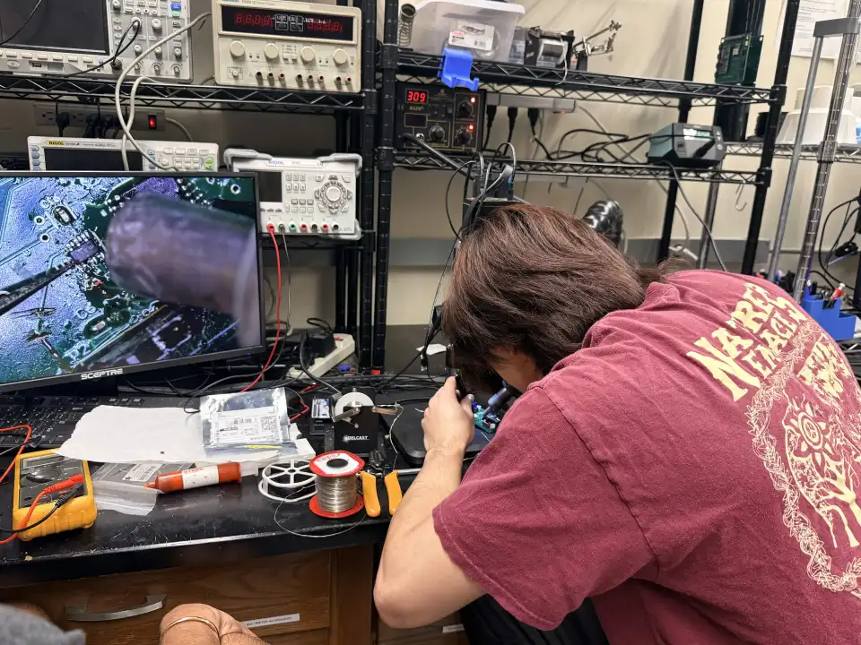
- The mouse broke on competition morning at Montclair 2026. An electrical fault stopped it, and the team competed without a working robot. The clip above is from before that.
The team traced the fault under the inspection microscope:
Who did what
I wrote and tested the 2026 firmware. Dennis Huang added the IMU setup code and speed plotting to DriverLab, and Felix Nie tuned the line follower. The electrical and mechanical members built the hardware; I helped with soldering and PCB design, not most of it. As captain I gave each member a component to own, with deadlines set at weekly builds. Placements belong to the team. Manasa filmed the run.